- 您现在的位置:买卖IC网 > Sheet目录102 > NHD-C0220AA-FSW-FTW (Newhaven Display Intl)LCD COG CHAR 2X20 WH TRANSFL
[4]?
?
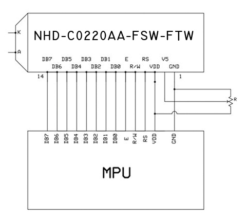
Pin?Description?and?Wiring?Diagram?
Pin?No.?
Symbol?
External?
Connection?
Function?Description
1?
GND?
Power?Supply?
Ground
2?
V5?
Adj?Power?Supply?
Contrast?voltage?adjustment?(~0.1V)
3?
VDD?
Power?Supply?
VDD=3.3V
4?
RS?
MPU?
Register?Select:?0=Instruction,?1=Data
5?
R/W?
MPU?
Read?/?Write?select:?0=Write,?1=Read
6?
E?
MPU?
Read/Write?start?signal?(Schmitt?trigger?input)
7‐10?
DB0?–?DB3?
MPU?
Low?4?tri‐state?bi‐directional?data?bus?lines.?Not?used?in?4‐bit?
mode.?
11‐14?
DB4?–?DB7?
MPU?
High?4?tri‐state?bi‐directional?data?bus?lines.
Recommended?LCD?connector:?2.0mm?pitch,?14pins?Soldered?to?PCB,?or?JST?p/n:?PHR‐14?
Backlight?connector:?A?and?K?pins?Mates?with:?Solder?to?wires?or?PCB?
?
?
?
?
?
?
?
?
?
?
?
?
?

发布紧急采购,3分钟左右您将得到回复。
相关PDF资料
NHD-C0220AU-FSW-FTS
LCD COG CHAR 2X20 WH TRANSFL
NHD-C0220AZ-FSW-FTW
LCD COG CHAR 2X20 WH TRANSFL
NHD-C0220BIZ-FSW-FBW-3V3M
LCD COG CHAR 2X20 WH TRANSFL
NHD-C128128BZ-FSW-GBW
LCD COG GRAPH 128X128 WH TRANSFL
NHD-C128128CZ-FN-GBW
LCD MOD GRAPH 128X128 TRANSFL
NHD-C12832A1Z-FSB-FBW-3V3
LCD COG GRAPH 128X32 BLUE BKLT
NHD-C12832A1Z-FSR-FBW-3V3
LCD COG GRAPH 128X32 RED BKLT
NHD-C12832A1Z-FSW-FBW-3V3
LCD COG GRAPHIC 128X32
相关代理商/技术参数
NHD-C0220AA-FSW-FTW (3V)
制造商:NEWHAVEN DISPLA 功能描述:DISPLAY,COG LCD,20x2,PARALLEL, BLK-WHT,3.3V,TRANSREFLECTIVE
NHD-C0220AU-FSW-FTS
功能描述:LCD字符显示模块与配件 2 x 20 FSTN (+) 74.5 x 25.0 x 6.20 RoHS:否 制造商:Lumex 显示模式:Transflective 字符计数 x 行:16 x 2 特点: 流体类型:STN 接口: 背景色: 工作温度范围:- 20 C to + 70 C 封装:Bulk
NHD-C0220AZ-FSW-FTW
功能描述:LCD字符显示模块与配件 FSTN (+) Transfl 74.5 x 25.0 x 6.20 RoHS:否 制造商:Lumex 显示模式:Transflective 字符计数 x 行:16 x 2 特点: 流体类型:STN 接口: 背景色: 工作温度范围:- 20 C to + 70 C 封装:Bulk
NHD-C0220BIZ-FS(RGB)-FBW
制造商:NEWHAVEN DISPLA 功能描述:20x2 Character Liquid Crystal Display Module
NHD-C0220BiZ-FS(RGB)-FBW-3VM
功能描述:LCD字符显示模块与配件 2 x 20 FSTN (+) Transf RGB LED RoHS:否 制造商:Lumex 显示模式:Transflective 字符计数 x 行:16 x 2 特点: 流体类型:STN 接口: 背景色: 工作温度范围:- 20 C to + 70 C 封装:Bulk
NHD-C0220BiZ-FSW-FBW-3V3M
功能描述:LCD字符显示模块与配件 2 x 20 FSTN (+) Transf White LED RoHS:否 制造商:Lumex 显示模式:Transflective 字符计数 x 行:16 x 2 特点: 流体类型:STN 接口: 背景色: 工作温度范围:- 20 C to + 70 C 封装:Bulk
NHD-C-128128BZ-FSW-GBW
功能描述:LCD COG GRAPH 128X128 WH TRANSFL RoHS:是 类别:光电元件 >> 显示器模块 - LCD,OLED,图形 系列:NHD-C-128128BZ-F 标准包装:1 系列:* 其它名称:Q7143510
NHD-C128128BZ-FSW-GBW
功能描述:LCD 图形显示模块和配件 128 x 128 STN-GRAY 71.3 x 75.41 x 6.0 RoHS:否 制造商:ELECTRONIC ASSEMBLY 产品: 分辨率:128 x 64 流体类型:FSTN Positive 接口: 背光: 背景色:White 工作温度范围:- 20 C to + 70 C 封装:Bulk
